New and better approach for
Adjusting the side mounted
Kalart Rangefinder.
In previous published instructions I presumed that the long arm or cam which follows the movement of the track and thus the lens, was correctly connected to the rangefinder. Unfortunately this seems not always to be the case. This new instructions will show you the working and adjusting of the whole range finding mechanism rather than just calibrating the Rangefinder as an isolated instrument. The correct connection to the track is essential for the good working. I hope that herewith your Kalart Rangefinder adjusting will be brought to a successful end.
Follow these instructions step by step
Step I
First find the infinity setting of the lens standard.
First of all we have to know that the adjustment can be made for only one lens of your choice. Each different focal length of the lens needs its own adjustment. On Speed Graphic camera, lenses can be used of different length. From 127 mm up to 6 3/8 inch.
Put the camera on a tripod. Open the front door of the camera and turn the lock of the standard strait and pull out the standard against the infinity stops. Open the back and make sure that the focal plane shutter (if mounted) is in "O" open position. Set front shutter in "T" position. Cock the shutter and trip the trigger. The front shutter is open now and you should see an image on the ground glass. Aim on a far away object like a church tower and check if the image on the ground glass is sharp. Only if you are really satisfied with a crispy sharp image you may allow yourself to skip the next step.
Unscrew the infinity stops and slide them some inches to the front of the track.
Aim the camera on a subject far away. Grab the front
standard lock and swing it strait.
While watching the ground glass move the front standard for and backwards until
the object is in focus and the image on the ground glass is crispy sharp.
Swing the standard lock to the left or the right to lock the
standard and thus fixing it in this position.
Raise the hinged infinity stops and slide them back against the standard and fix
them both with the tiny screw on the front side. Unlock standard push standard
backwards and tighten the
rear screws of the infinity stops. Pull standard forwards firmly against the
infinity stops and lock the standard. Check again the image on the ground glass to
be sure the position of the infinity stops did not changed. To be sure the standard
will be locked at the right angle you may
check the infinity stops position by measuring the distance from the end of the
track to the infinity stop. This distance should be equal for both infinity
stops.
Step II
Infinity setting of the Kalart Rangefinder
Long Cam and
synchronizing with the track.
Remove the Aero lens by sliding back the upper and lower slide locks of the standard. Put the lens apart on a safe place.
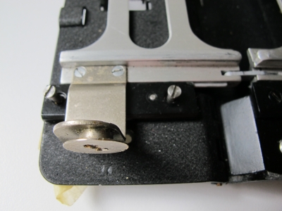
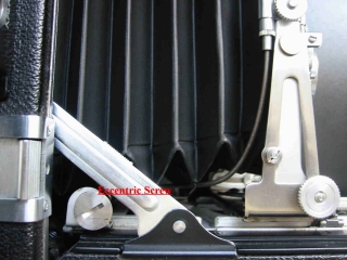
Turn out the track as far as necessary so that it enables you to adjust the eccentric screw
mounted on the back of the
track.
Set the eccentric screw with the groove in vertically position thus giving you later
the
opportunity to make corrections to the left or the right.
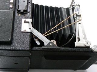
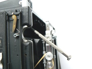
The left photo shows the long cam connected with a rubber string to the front standard.
On front of the long cam the eccentric screw.
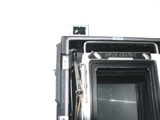
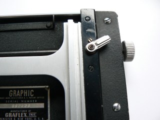
The right photo shows the nut driver on the set screw.
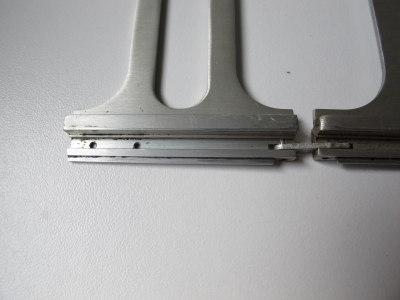
Left photo: the position of the two holes for mounting the eccentric screw bracket.
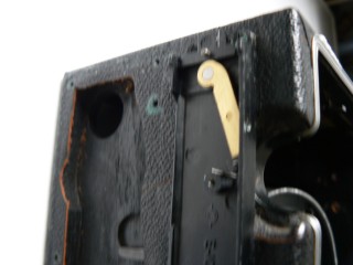
There is an arm or long cam coupled to the Kalart Rangefinder shaft which follows the eccentric screw when it moves for and backwards during the focusing procedure. This arm is connected to the rangefinder cam-shaft by a set screw. Loosen this screw just a bit but make sure that the cam stays in position on the cam shaft and wont come off. Put a rubber string around the lower end of the cam and the other end of the string around the knob of the frame clamp.
Having done that, turn the track all of the way back into the camera body with the focusing knob.
Now remove the Kalart Rangefinder housing. This can be done by unscrewing the two screws on top of the housing. However, this depends on how your Kalart is mounted, with or without the Rangefinder Encircling Bracket. The last one is fitted by two more screws inside the camera body and one more on top of the camera body. The "Focuspot" if mounted, should be removed with care and patience.
Now lift the Kalart housing straight off from the base plate and the Kalart Main Plate becomes visible.
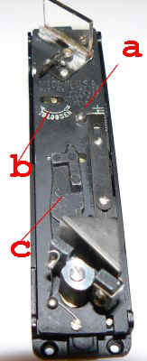
In the centre of the Main Plate there is a round-head screw (a) right under the hexagonal head adjusting screw (b) "to loosen". Lay the camera on its left side ( (handle side) so that you can loosen the screw without the risk that the plate drops down. The Main Plate is free now and ca be lifted from the Base Plate. You'll see now the bras cam shaft sub-assembly. This cam moves synchronically with the movement of the main cam in the camera house. The bras cam on its turn controls the fulcrum bar assembly of the prism.
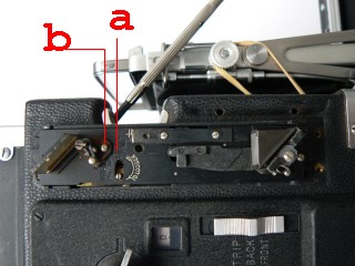
To adjust the Rangefinder on infinity we have to set the bras cam on a certain position on the base plate. The bras cam is positioned against the right side of the plate. Now move with your finger the spring loaded bras cam to the left until it leaves 9 mm free space on the left. Now turn the set screw of the large arm clockwise tight on the shaft of the long cam inside the camera house. The bras cam should now hold that position.
Turn the track one turn forward and you'll see that the bras cam moves to the right. Stop this action to disengage the rubber spring. Now you can turn the track as far as you like and back again. Make sure that the bras cam stops 9 mm from the left while the track is all the way back in the camera house. If that is not so, please repeat the instructions.
This should be the situation when the cam has been turned out at its maximum. The bras cam is then forced against the right side of the rangefinder plate.
The big cam protrudes about 5 mm outside the housing. Fine tuning can be done later with the eccentric screw.
Now we can rely on the good working an the right setting of the main cam and thus the bras cam on the base plate, it is time to reassemble the Rangefinder.
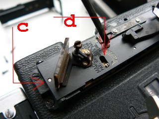
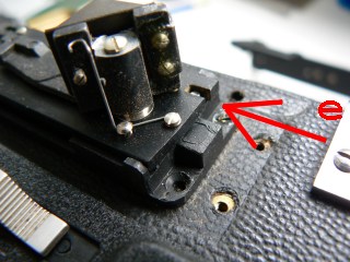
Carefully replace the Main Plate while holding the hexagonal head adjusting screw (d) to the left, allowing the fulcrum bar to find its place between the brass cam and the edge of the base plate. Make sure that the little hole in the main plate (c) falls into the pin on the base plate and on the lower side of the main plate the groove (e) fits to the pin of the base plate. When turning the focus-knob we can see that the prism assembly is moving. Time to clean the windows of the Kalart housing and replace the cover. Due to the relative soft silver coating, silver coated mirrors must be cleaned only with silk cloth. Please do not rub this surface as it will go off very easy and the rangefinder would be totally useless.
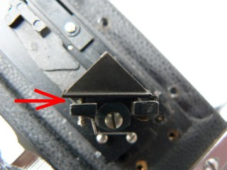
The prism should be positioned with a maximum of 1 to 2 mm mm of space between the back of the prism assembly and the prism itself.
For a brighter view it may be a good idea to clean the round windows of the rangefinder-house from the in and outside.
The infinity adjustment is made by turning the eccentric screw attached to the rear of the right runner of the camera track.
Move this screw very slightly back to raise the movable image and forward to lower the movable image.
Step III
More adjusting has to be done.
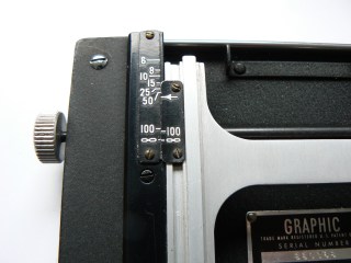
As the Rangefinder cover or housing is not yet replaced, the rangefinder mechanism is still unprotected so please be careful while handling the camera. Put the camera back on the tripod again and replace the lens. Pull the standard firmly against the infinity stops and lock the lens standard. Lock the track-lock which can be found on the right side next to the right focusing knob, by swinging it to the right. Check the focusing scale whether both infinity signs are opposite each other. If not, calibrate the focusing scale by loosening the two screws from the distance-scale on the track 1-2 turns and by sliding it in such a way that the both infinity signs are opposite each other. Fasten the screws again.
Note that the focusing scales for such a camera and lens combination will align properly only when the bed is in the correct focusing position. That means not in drop bed position for lenses with a greater focusing length than 90 mm. It is a good practice to verify the focusing scale against the ground glass by checking the sharpness at infinity. If both agree then you can proceed to use the scale for all distances.
Reliable focusing on the ground glass as well as focusing by reading out the focusing scale is now available. However, we still have to adjust the rangefinder for the specific lens we want to mount. As we did not replace the cover of the Kalart Rangefinder yet, we still have good access to all the adjustment controls we might need.
Step IV
Fine tuning of the Kalart Rangefinder.
Let us start checking whether the track and the standard are still in infinity position and the track is turned back all the way in the housing. Now we can make an approximate pre-adjustment of the short front scale of the indicator assembly and the long rear scale of the fulcrum bar indicator to suit the lens focal length. To set the back scale loosen (attention to loosen turn right) screw no. 2 by giving it one quarter turn to the direction indicated and move the indicator 4 to the desired setting. Then tighten the screw. To set the front scale loosen the two screws 1 and move the indicator to the given number 3.
|
Film Size |
Lens | Long rear scale | Short front scale indicator |
| 4x5 inch | 127 mm ƒ 4,7 | 13 | 3 |
| 135 mm ƒ 4,5 | 15 | 3,5 | |
| 165 mm ƒ 4,5 | 19 | 6 | |
| 6 3/8 inch ƒ 2,9 | 17 | 6 |
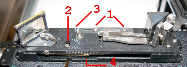
Infinity setting made by eccentric screw.
Having done that we should find the infinity position of the Kalart Range Finder
prism by turning the eccentric screw. Before
doing that place your camera set-up in a dimmed room with no window on the rear.
Try to find a bright subject at least a mile away and aim the camera on it.
While looking through the beam splitter or silvered mirror you may try to find
the double image becomes visible trough the mirror. While still watching the
chosen subject, move the camera up en down until you clearly see two images of
the subject. Fix the camera on that point. Now the infinity adjustment is made
by turning the eccentric screw attached to the rear of the right runner of the
camera track. Move the screw slightly back to raise the movable image and
forward to lower the movable image. Turn the focusing knob back again and check
your last change through the rangefinder. This has to be repeated until the
image coincides.
Step V
Fine tuning.
The previous described rough adjustment is just the start for a finer reliable adjustment. However, as we already pre-adjusted both rear and front indicators, one could be surprised to find out that all the other adjustments are redundant. Never the less let's continue assuming that we may have not so much luck.
Set the adjustments scales for the lens to be used as listed in the table above. To set the back scale loosen screw no. 2 by giving it one quarter turn to the direction indicated and move the indicator 4 to the desired setting. Then tighten the screw. The camera is then focused on a flat object approximately 25 ft away. Use a magnifying glass to make absolutely certain of the sharpness of the image on the ground glass and then view the image through the rangefinder. If the images are in coincide repeat this test with the camera focused at 15 feet. If at either of both of these distances the rangefinder is not in focus, an adjustment is made on the rear scale.
When the movable image is high, the indicator is moved down slightly. When the movable image is low, the indicator is raised slightly. After this adjustment, re-check the rangefinder at infinity. If the infinity adjustment has shifted, bring it back to focus by following the instructions previous given under Step IV Infinity setting made by eccentric screw. Check the rangefinder at 25 feet and 15 feet again and if the images are not in coincide repeat the above directions until coincide is attained. This method is necessary in order to adjust the rangefinder to the exact focal length of you individual lens rather than to an arbitrary adjustment which would only approximate sharp focus.